당신은 주제를 찾고 있습니까 “srm 모터 – SynRM | 전기 세계의 새로운 거인“? 다음 카테고리의 웹사이트 https://hu.taphoamini.com 에서 귀하의 모든 질문에 답변해 드립니다: https://hu.taphoamini.com/photos/. 바로 아래에서 답을 찾을 수 있습니다. 작성자 Lesics 이(가) 작성한 기사에는 조회수 4,443,176회 및 좋아요 72,729개 개의 좋아요가 있습니다.
Table of Contents
srm 모터 주제에 대한 동영상 보기
여기에서 이 주제에 대한 비디오를 시청하십시오. 주의 깊게 살펴보고 읽고 있는 내용에 대한 피드백을 제공하세요!
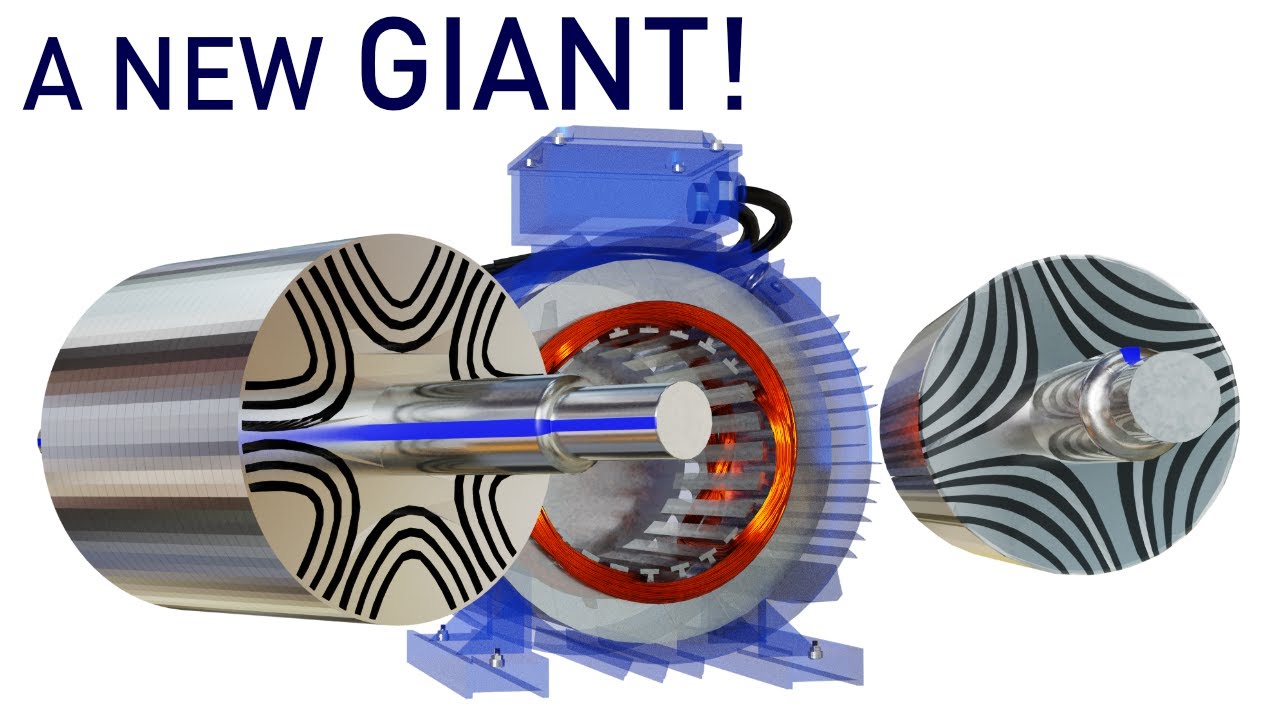
d여기에서 SynRM | 전기 세계의 새로운 거인 – srm 모터 주제에 대한 세부정보를 참조하세요
With the advent of advanced control algorithms SynRMs are getting super popular across all the industries. Let’s understand the physics and design features of SynRMs in detail.
We thank EMWorks for their FEA support. To know more about this powerful electromagnetic simulation software checkout : https://www.emworks.com/
For those who want to delve deeper into SynRMs here are few links
1) SynRM’s potential uses in the industries – https://youtu.be/3g9lDqkCP3g
2) Interesting control logics of SynRm – https://youtu.be/ZOH1PoOOeuY
3) Torque comparison SynRm vs IMs – https://ieeexplore.ieee.org/document/1518350
4) The latest trends – https://www.plantservices.com/articles/2020/why-permanent-magnet-motors-and-reluctance-motors-are-finding-increased-industry-application/
Be our supporter or contributor: https://www.youtube.com/channel/UCqZQJ4600a9wIfMPbYc60OQ/join
instagram : https://www.instagram.com/sabinzmathew/
Twitter : https://twitter.com/sabinsmathew
Telegram : https://t.me/sabinmathew
FB : https://www.facebook.com/SabinzMathew
Voice over artist : https://www.fiverr.com/voiceonthemove
srm 모터 주제에 대한 자세한 내용은 여기를 참조하세요.
스위치드 릴럭턴스 전동기(SRM) 구동용 Converter Topology 연구
A Study on Converter Topology to Drive Switched Reluctance Motor (SRM) – SRM;Converter Topology;Efficiency;Performance;Simplify.
Source: www.kci.go.kr
Date Published: 10/15/2022
View: 8146
스위치드 릴럭턴스 전동기 (SRM) 회전자 위치 검출 및 초기 위치 …
Position for Switched Reluctance Motor (SRM). 정성인*. Sungin Jeong*. 요 약 브러시리스 DC 전동기(BLDC)는 스위치의 on/off 각이 최적의 고정자 …
Source: www.koreascience.or.kr
Date Published: 5/13/2021
View: 3098
Switched reluctance motor – Wikipedia
The switched reluctance motor (SRM) is an electric motor that runs by reluctance torque. Unlike common brushed DC motor types, power is delivered to …
Source: en.wikipedia.org
Date Published: 10/20/2021
View: 1968
Switched reluctance motor, SR MOTOR, 김중교,모터,MOTOR …
Ⅰ.SRM (Switched Reluctance Motor). 기본 구조. . 고정자 : 적층 철심에 집중권의 권선을 가짐 회전자 : 권선 없이 적층 철심으로만 구성됨
Source: m.blog.naver.com
Date Published: 2/26/2022
View: 227
Switched Reluctance (SR) 모터의 특성 및 작동 원리
SR 모터 특성 SR (Switched Reluctance) 모터는 고정자와 회 전자에 모두 돌출 극이 … Switched Reluctance Motor 정면도 (사진 크레디트 : engineering.zhaw.ch).
Source: crushtymks.com
Date Published: 8/18/2021
View: 5198
Srm 제어 방법 및 이러한 방법을 사용하는 장치
SRM 제어 방법 및 이러한 방법을 사용하는 장치가 개시되어 있다. SRM(switched reluctance motor)의 구동 제어 방법은 SRM의 부하 변동을 감지하는 단계, SRM의 부하 …
Source: patents.google.com
Date Published: 8/11/2021
View: 2753
[논문]고속회전을 지원하는 SRM형 BLDC 모터 제어알고리즘 및 …
또한 BLDC 모터의 값비싼 마그넷 회전자는 SRM형으로 대치되고 있는데 SRM은 시스템의 허용범위 내에서 전류값이 넘지 않도록 해야하는 제어를 요구한다. 본 논문에서는 …
Source: scienceon.kisti.re.kr
Date Published: 5/24/2021
View: 6029
주제와 관련된 이미지 srm 모터
주제와 관련된 더 많은 사진을 참조하십시오 SynRM | 전기 세계의 새로운 거인. 댓글에서 더 많은 관련 이미지를 보거나 필요한 경우 더 많은 관련 기사를 볼 수 있습니다.
주제에 대한 기사 평가 srm 모터
- Author: Lesics
- Views: 조회수 4,443,176회
- Likes: 좋아요 72,729개
- Date Published: 2020. 9. 30.
- Video Url link: https://www.youtube.com/watch?v=vvw6k4ppUZU
스위치드 릴럭턴스 전동기(SRM) 구동용 Converter Topology 연구
스위치드 릴럭턴스 전동기 (Switched Reluctance Motor, SRM)는 전류의 크기와 회전자와 고정자의 상대적위치에 따라 인덕턴스가 매우 비선형적으로 변하는 특성이 있고, 토크는 이 인덕턴스의 기울기에 비례하여 발생하기 때문에 비선형 토크 특성을 가지며 토크 맥동이 크고 소음이 심한 단점도 있다. 이러한 문제점들을 고려하고 경제성과회로의 간단화를 위하여 기존의 비대칭 컨버터 (Asymmetric Bridge Converter)에서 효율과 성능을 개선할 수 있는구동용 토폴로지(Topology)에 대한 연구들이 많이 진행되었다. 따라서 본 논문에서는 SRM 구동용 토폴로지로 적용하여 사용되고 있는 각 컨버터들을 비교, 분석함으로써 성능을 확인하고자 한다. 비교, 분석에 적용된 구동용 컨버터는가장 널리 사용되고 있는 비대칭 브리지 컨버터 (Asymmetric Bridge Converter)와 C-dump 컨버터 형태의 구조를가진 Conventional C-dump, Modified C-dump, Energy efficient C-dump, 공진형 C-dump 컨버터, 그리고 일반 전동기의 범용으로 사용되고 있는 6-Switch 인버터이다.
Switched Reluctance Motor (SRM) has a characteristic that the inductance changes very nonlinearly depending on the magnitude of the current and the relative position of the rotor and stator, and the torque is generated In consideration of these problems, many studies have been conducted on a topology for driving that can improve efficiency and performance in an existing asymmetric bridge converter in order to simplify the circuit and economic efficiency. Therefore, in this paper, we want to check the performance by comparing and analyzing each converter used by applying it as a topology for SRM driving. The driving converters applied to the comparison and analysis are Conventional C-dump, Modified C-dump, Energy efficient C-dump, Resonant C-dump converter with C-dump converter type structure and the most widely used asymmetric bridge converter and 6-Switch inverter that used for general motors.
Switched reluctance motor
Type of electric motor that runs by reluctance torque
The switched reluctance motor (SRM) is an electric motor that runs by reluctance torque. Unlike common brushed DC motor types, power is delivered to windings in the stator (case) rather than the rotor. This greatly simplifies mechanical design as power does not have to be delivered to a moving part, but it complicates the electrical design as some sort of switching system needs to be used to deliver power to the different windings. Electronic devices can precisely time the switching of currents, facilitating SRM configurations. Its main drawback is torque ripple.[1] Controller technology that limits torque ripple at low speeds has been demonstrated.[2] Sources disagree on whether it is a type of stepper motor.[3]
The same electromechanical design can be used in a generator. The load is switched to the coils in sequence to synchronize the current flow with the rotation. Such generators can be run at much higher speeds than conventional types as the armature can be made as one piece of magnetisable material, as a slotted cylinder.[4] In this case the abbreviation SRM is extended to mean Switched Reluctance Machine, (along with SRG, Switched Reluctance Generator). A topology that is both motor and generator is useful for starting the prime mover, as it saves a dedicated starter motor.
History [ edit ]
The first patent was by W. H. Taylor in 1838 in the United States.[5][6]
The principles for SR drives were described around 1970,[7] and enhanced by Peter Lawrenson and others from 1980 onwards.[8] At the time, some experts viewed the technology as unfeasible,[9] and practical application has been limited, partly because of control issues and unsuitable applications, and because low production numbers result in higher cost.[10][1][11]
Operating principle [ edit ]
The SRM has wound field coils as in a DC motor for the stator windings. The rotor however has no magnets or coils attached. It is a solid salient-pole rotor (having projecting magnetic poles) made of soft magnetic material (often laminated steel). When power is applied to the stator windings, the rotor’s magnetic reluctance creates a force that attempts to align the rotor pole with the nearest stator pole. In order to maintain rotation, an electronic control system switches on the windings of successive stator poles in sequence so that the magnetic field of the stator “leads” the rotor pole, pulling it forward. Rather than using a mechanical commutator to switch the winding current as in traditional motors, the switched-reluctance motor uses an electronic position sensor to determine the angle of the rotor shaft and solid state electronics to switch the stator windings, which enables dynamic control of pulse timing and shaping. This differs from the apparently similar induction motor that also energizes windings in a rotating phased sequence. In an SRM the rotor magnetization is static (a salient ‘North’ pole remains so as the motor rotates) while an induction motor has slip (rotates at slightly less than synchronous speed). SRM’s absence of slip makes it possible to know the rotor position exactly, allowing the motor to be stepped arbitrarily slowly.
Simple switching [ edit ]
If the poles A0 and A1 are energised then the rotor will align itself with these poles. Once this has occurred it is possible for the stator poles to be de-energised before the stator poles of B0 and B1 are energized. The rotor is now positioned at the stator poles b. This sequence continues through c before arriving back at the start. This sequence can also be reversed to achieve motion in the opposite direction. High loads and/or high de/acceleration can destabilize this sequence, causing a step to be missed, such that the rotor jumps to wrong angle, perhaps going back one step instead of forward three.
Quadrature [ edit ]
A much more stable system can be found by using a “quadrature” sequence in which two coils are energised at any time. First, stator poles A0 and A1 are energized. Then stator poles B0 and B1 are energized which, pulls the rotor so that it is aligned in between A and B. Following this A’s stator poles are de-energized and the rotor continues on to be aligned with B. The sequence continues through BC, C and CA to complete a full rotation. This sequence can be reversed to achieve motion in the opposite direction. More steps between positions with identical magnetisation, so the onset of missed steps occurs at higher speeds or loads.
In addition to more stable operation, this approach leads to a duty cycle of each phase of 1/2, rather than 1/3 as in the simpler sequence.
Control [ edit ]
The control system is responsible for giving the required sequential pulses to the power circuitry. It is possible to do this using electro-mechanical means such as commutators or analog or digital timing circuits.
Many controllers incorporate programmable logic controllers (PLCs) rather than electromechanical components. A microcontroller can enable precise phase activation timing. It also enables a soft start function in software form, in order to reduce the amount of required hardware. A feedback loop enhances the control system.[1]
Power circuitry [ edit ]
Asymmetric bridge converter
The most common approach to powering an SRM is to use an asymmetric bridge converter. The switching frequency can be 10 times lower than for AC motors.[3]
The phases in an asymmetric bridge converter correspond to the motor phases. If both of the power switches on either side of the phase are turned on, then that corresponding phase is actuated. Once the current has risen above the set value, the switch turns off. The energy now stored within the winding maintains the current in the same direction, the so-called back EMF (BEMF). This BEMF is fed back through the diodes to the capacitor for re-use, thus improving efficiency.[12]
N+1 switch and diode
This basic circuitry may be altered so that fewer components are required although the circuit performs the same action. This efficient circuit is known as the (n+1) switch and diode configuration.
A capacitor, in either configuration, is used for storing BEMF for re-use and to suppress electrical and acoustic noise by limiting fluctuations in the supply voltage.
If a phase is disconnected, an SR motor may continue to operate at lower torque, unlike an AC induction motor which turns off.[7][13]
Applications [ edit ]
SRMs are used in some appliances.[14]
Switched reluctance motor, SR MOTOR, 김중교,모터,MOTOR,전동기,제어용 모터
Ⅰ.SRM (Switched Reluctance Motor)
기본 구조
고정자 : 적층 철심에 집중권의 권선을 가짐
회전자 : 권선 없이 적층 철심으로만 구성됨
돌극구조: 고정자와 회전자는 Reluctance Torque의 극대화를 위해 보통 돌극(Sailent)구조로 설계함
구동 Drive : 인버터로 스위칭 제어/구동
SRM 기본 이론
SRM 기본 이론
그림)은 rotor의 전기전 1주기의 이동에 따른 토크 발생 구간을 보여준다.
unligned 위치에서 rotor가 stator의 pole과 중첩되기 시작하는 순간 인덕터(L)이 증가하기 시작하고, 정토크가 발생한다.
이 구간동안에 반도체 스위칭 소자를 on 시켜 전류를 흘려 토크를 발생시키고, 이구간을 Dwell region이라고 부른다.
rotor와 starot의 pole이 완전히 중접된 aligned구간에서는 인덕터의 변화가 없고 토크도 발생하지 않는데 이 구간을 Dead Zone이라고 한다.
이 구간에서의 에너지주입은 토크의 발생이 없으므로 저장되었다가, 다음구간에 전원 측으로 회생된다. SRM의 설계시 이 구간이 거의 없도록 설계하여야한다.
rotor가 stator의 pole을 이탈하기 시작하는 순간 인덕터(L)이 감소하기 시작하고, Motor는 generator처럼 동작하고, 역 토크가 발생하게 된다.
이 구간을 tail구간이라고 하며 , 가급적 작게 되도록 Drive를 설계하여야하며, 이 구간이 SRM의 토크 ripple을 많이 발생하게 된다.
이 구간에서 발생된 에너지는 전원측으로 일부는 회생되고, 일부는 역토크를 발생시키는데 소모된다.
역토크 발생 구간에서는 전류를 흐르지 않게 함으로써 역토크 발생을 억제할 필요가 있고, 이러한 방법은
SRM의 Drive에서 구현된다.
Switched Reluctance (SR) 모터의 특성 및 작동 원리
SR 모터 특성
스위치드 릴럭 턴스 (SR) 모터는고정자와 회 전자 둘 다 돌출 극을 가지고 있기 때문에 설명 된 다른 다상 기계와는 다릅니다. 모터는 특정 전력 변환기 및 제어 장치와 함께 사용해야 만하므로 전체 특성 만 관련됩니다.
Switched Reluctance (SR) 모터의 특성 및 작동 원리 (사진 = machinedesign.com)
SR 모터는 자기인덕터는 고정자 전자석과 강자성체로만 이루어진 간단한 회 전자에 형성된 돌출 극 세트 사이에서 발생합니다.
토크 생산의 직관적 인 직선 원리는 그림과 같이 매우 단순한 릴럭 턴스 모터에서 쉽게 시각화됩니다. 그림 1.
그림 1 – 단순한 릴럭 턴스 모터
전류가 권선에 가해지면 로터코일과 정렬되는 위치에 도달 할 때까지 회전하며,이 지점에서 자기 회로의 인덕턴스는 최소가된다. SR 모터의 인덕턴스의 특성 변화는 그림 2.
그림 2 – 회 전자 각도의 인덕턴스 변화
기계가 가볍게 자기 적으로 적재되고적당한 수준의 토크가 발생되면 로터와 스테이터가 만들어진 강철은 대략 선형으로 자기 적으로 거동하게됩니다.
각도 θ의 함수 : 즉, 주어진 턴 수만큼위상의 자속은 위상 전류에 대략 비례하여 변화한다. 선형성이 가정된다면, 다음과 같이 생산 된 토크가: p> T = [i2 (dL / dθ)] / 2 위의 등식은 토크가 전류의 방향에 의존하지 않지만 전류가인가 될 때 적용되는지 여부에 달려 있음을 보여줍니다. 인덕턴스 L 각도 위치로 상승 또는 하강합니다.
위상 전류는 항상 회 전자의 기계적 위치와 동기식으로 전환됩니다. 저속에서, 위상은상승하는 인덕턴스의 전체 영역, 컨트롤러에서 능동 전류 제한이 필요합니다. 토크는 위상 전류의 크기를 조정하여 제어됩니다.
SR 모터 – 분해도
속도가 증가함에 따라, 상승 및 하강 시간(특히 후자)는 상당한 회 전자 각도를 차지하며, 회 전자 위치에 대해 턴온 및 턴 오프 각도를 앞당기는 것이 통상적이다. 전류는 일반적으로 주 제어 변수로 사용되지만 토크는 전류 제한 레벨과 스위칭 각도에 의해 제어됩니다. 고속에서는 상승 및 하강 시간이 여전히 더 큰 회 전자 각도를 차지합니다.
현재의 자연스런 자기 한계와 평상시입니다.스위칭 각만을 사용하여 토크를 제어합니다. 전류 파형의 모양은 시간에 대한 인덕턴스의 높은 변화율에 크게 영향을받습니다.
선택하여 적절한 스위칭 각과 전류 레벨, 적절한 전자기파와 함께디자인을 사용하면 스위치드 릴럭 턴스 드라이브의 토크 – 속도 특성을 애플리케이션에 맞출 수 있습니다. 또한 토크 및 속도로 제어 매개 변수 선택을 변경함으로써 주어진 기계 설계를 통해 다양한 특성을 선택할 수 있습니다.
그림 3 – 3 상 6-4 SR 모터 단면도
간단한 단상 기계 그림 1 단지 절반의 토크를 생산할 수있다.그것의 전기주기. 더 까다로운 어플리케이션은 로터와 고정자에 더 높은 극 수를 사용하고 고정자 극은 감아 서 여러 개의 동일한 위상으로 연결됩니다. 그림 3 도 3은 3- 상 6-4 기계의 단면을 도시하며, 직경 방향으로 대향 된 코일은 A, B 및 C로 표시된 3 상 회로를 형성한다..
위상의 여기 (excitation)는 인터리브기계의 전기적 기간 전체에 걸쳐 동일하게 적용됩니다. 이는 원하는 극성의 토크가 연속적으로 생성 될 수 있음을 의미합니다. 이론적으로 상수는 제한없이 증가 할 수 있지만 1 ~ 4 단계는 상업 및 산업 분야에서 가장 일반적입니다.
폴 카운트의 많은 다른 조합이 가능합니다. 위상마다 하나 이상의 고정자 극 쌍을 사용하는 것이 가끔 유용하기 때문에, 예를 들어, 12-8 극 구조 3 상 어플리케이션에 일반적으로 사용됩니다. 각각의 위상 회로는 함께 연결되고 통전되는 4 개의 고정자 코일을 포함한다. 위상 수를 늘리면보다 부드러운 토크를 얻을 수 있습니다.
양방향으로자가 시동 필요 적어도 세 단계.
응용 및 장점 p> 이러한 스위치드 릴럭 턴스 모터 드라이브는 대용량 기기 그 특성을 잘 활용할 수있는 산업 응용 분야, 특히 높은 시동 토크 그리고 회전의 매끄러움에 덜 중요하게 둔다. 이 드라이브의 소음 특성을 향상시키는 데 상당한 진보가 있었지만, 여전히 넓은 작동 속도 범위가 요구되는 제한 요소가 될 수 있습니다. 스위치드 릴럭 턴스 모터 어플리케이션 (사진 크레디트 : engineering.zhaw.ch) p>
Switched Reluctance Motor 정면도 (사진 크레디트 : engineering.zhaw.ch) p>
KR20140086496A – Srm 제어 방법 및 이러한 방법을 사용하는 장치 – Google Patents
H — ELECTRICITY
H02 — GENERATION; CONVERSION OR DISTRIBUTION OF ELECTRIC POWER
H02P — CONTROL OR REGULATION OF ELECTRIC MOTORS, ELECTRIC GENERATORS OR DYNAMO-ELECTRIC CONVERTERS; CONTROLLING TRANSFORMERS, REACTORS OR CHOKE COILS
H02P25/00 — Arrangements or methods for the control of AC motors characterised by the kind of AC motor or by structural details
H02P25/02 — Arrangements or methods for the control of AC motors characterised by the kind of AC motor or by structural details characterised by the kind of motor
[논문]고속회전을 지원하는 SRM형 BLDC 모터 제어알고리즘 및 성능분석에 관한 연구
예를 들어 선풍기, 에어컨디션, 냉장고, 컴프레셔, 원심분리기 등과 같은 대부분의 기기에는 모터가 사용되고 있다. 장착되는 모터는 Universal 모터에서 생기는 카본 분진 오염 문제와 브러시 교체등 유지보수비 및 짧은 수명 으로 인해 점차 Universal 모터에서 BLDC 모터나, SRM (Switched Reluctance Motor) 모터를 사용하는 기기의 수요가 증가하고 있다[1-3]. SRM 모터는 구조가 간단하고, 가격이 저렴하며 회전자의 허용온도가 매우 높고, 개방회로의 전압과 단락시의 전류가 영이거나 매우 작을 뿐만 아니라 높은 효율, 단위 부피 및 무게 당 높은 출력, 높은 토크 대비 비용, 넓은 속도 범위에 걸친 제어 능력, 우수한 신뢰성을 갖는 고속 동작 등으로 인해 환경보존을 위한 고효율에너지 장치에 대한 관심과 함께 가전산업에서 널리 주목을 받고 있다[3-5].
SRM 모터가 가진 장점에는 무엇이 있는가?
키워드에 대한 정보 srm 모터
다음은 Bing에서 srm 모터 주제에 대한 검색 결과입니다. 필요한 경우 더 읽을 수 있습니다.
이 기사는 인터넷의 다양한 출처에서 편집되었습니다. 이 기사가 유용했기를 바랍니다. 이 기사가 유용하다고 생각되면 공유하십시오. 매우 감사합니다!
사람들이 주제에 대해 자주 검색하는 키워드 SynRM | 전기 세계의 새로운 거인
- SynRM
- reluctance motor
- direct axis
- quadrature axis
SynRM #| #전기 #세계의 #새로운 #거인
YouTube에서 srm 모터 주제의 다른 동영상 보기
주제에 대한 기사를 시청해 주셔서 감사합니다 SynRM | 전기 세계의 새로운 거인 | srm 모터, 이 기사가 유용하다고 생각되면 공유하십시오, 매우 감사합니다.