당신은 주제를 찾고 있습니까 “5v regulator – 5V Regulator design tutorial – How it works, how to design PCB altium“? 다음 카테고리의 웹사이트 https://hu.taphoamini.com 에서 귀하의 모든 질문에 답변해 드립니다: https://hu.taphoamini.com/photos/. 바로 아래에서 답을 찾을 수 있습니다. 작성자 The Engineering Mindset 이(가) 작성한 기사에는 조회수 2,212,251회 및 좋아요 32,063개 개의 좋아요가 있습니다.
Table of Contents
5v regulator 주제에 대한 동영상 보기
여기에서 이 주제에 대한 비디오를 시청하십시오. 주의 깊게 살펴보고 읽고 있는 내용에 대한 피드백을 제공하세요!
d여기에서 5V Regulator design tutorial – How it works, how to design PCB altium – 5v regulator 주제에 대한 세부정보를 참조하세요
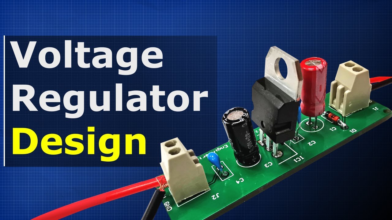
Voltage regulator. Learn how to make a 5V regulator using capacitors, LM7805 regulator and Schottky diode, learn how the circuit works and also how to build your own PCB printed circuit board, how to order a PCB and how to solder the boards electronic components together.
Get your own PCB!
🎁 PCB design software:➡️ https://www.altium.com/yt/theengineeringmindset
🎁 Only $2 for 5pcs 2 Layer \u0026 4Layer PCBs, Get SMT Coupon Here :➡️ https://jlcpcb.com/cyt
🎁 Download the PCB file:➡️ http://engmind.info/5v-reg-download
Good multimeter:➡️ http://electricl.info/good-multimeter
Pro multimeter:➡️ http://electricl.info/best-multimeter
Power monitor plug:➡️ http://engineerz.club/energy-plug
Parts list:
0.22 uF tinyurl.com/6cvd594z
0.1 uF tinyurl.com/52lje3ub
Regulator: tinyurl.com/yno56xth
Diode: tinyurl.com/1ndvfrey (choose another for higher current)
10 uF tinyurl.com/uom1r1wr
Connector tinyurl.com/1lfd249r
Watch these:
Diodes:➡️ https://youtu.be/Fwj_d3uO5g8
Capacitor:➡️ https://youtu.be/X4EUwTwZ110
👋 SOCIALISE WITH US 👋
*******************************
👉FACEBOOK: https://facebook.com/theengineeringmindset/
👉TWITTER: https://twitter.com/TheEngMindset
👉INSTAGRAM: https://instagram.com/engineeringmindset/
👉WEBSITE: Http://TheEngineeringMindset.com
👀 Links – MUST WATCH!! 👀
*******************************
⚡ELECTRICAL ENGINEERING⚡
👉How electricity works: https://youtu.be/mc979OhitAg
👉Three Phase Electricity: https://youtu.be/4oRT7PoXSS0
👉How Inverters work: https://youtu.be/ln9VZIL8rVs
👉How TRANSFORMER works: https://youtu.be/UchitHGF4n8
👉How 3 Phase electricity works: https://youtu.be/4oRT7PoXSS0
👉How Induction motor works: https://youtu.be/N7TZ4gm3aUg
👉What is a KWH: https://youtu.be/SMPhh8gT_1E
👉How induction motor works: https://youtu.be/N7TZ4gm3aUg
❄️ CHILLER ENGINEERING ❄️
👉Chiller Efficiency improvements: https://youtu.be/8x3MiO5XjhY
👉Chilled water schematics: https://youtu.be/ak51DHAiuWo
👉Chiller crash course: https://youtu.be/K0xAKzdROEg
👉Chiller types: https://youtu.be/gYcNDT1d30k
👉Chillers/AHU/RTU: https://youtu.be/UmWWZdJR1hQ
👉Water cooled chiller Part1: https://youtu.be/0rzQhSXVq60
👉Water cooled chiller Part2: https://youtu.be/3ZpE3vCjNqM
👉Water cooled chiller advanced: https://youtu.be/QlKSGDgqGF0
👉Air cooled chiller: https://youtu.be/0R84hLprO5s
👉Absorption Chiller : https://youtu.be/Ic5a9E2ykjo
👉Chiller/Cooling tower/AHU: https://youtu.be/1cvFlBLo4u0
👉Chiller flow rate: https://youtu.be/tA1_V6-dThM
👉Chiller fault troubleshooting: https://youtu.be/Zu0LVVNNVSw
👉Chiller COP calculation: https://youtu.be/h5ILlZ8nyHE
👉Chiller cooling capacity calcs: https://youtu.be/BZxXIdxVKeY
👉Chiller compressors: https://youtu.be/7Bah__spkTY
👉Chiller expansion valve: https://youtu.be/dXiV5YzTZQ4
👉Chiller surge: https://youtu.be/DQK_-vxObiw
👉Chiller condenser: https://youtu.be/p5uuPsyqnwU
👉Chiller evaporator: https://youtu.be/W3w7FpX9j9k
👉Chiller compressor centrifugal: https://youtu.be/PT0UIqAGacg
👉Chiller cooling capacity: https://youtu.be/f-N4isgQRGQ
🌡️ HVAC ENGINEERING 🌡️
👉HVAC Basics: https://youtu.be/klggop60vlM
👉Boilers/AHU/FCU: https://youtu.be/lDeuIQ4VeWk
👉How Heat Pump works: https://youtu.be/G53tTKoakcY
👉Heat pumps advanced: https://youtu.be/G53tTKoakcY
👉Fan Coil Units: https://youtu.be/MqM-U8bftCI
👉VAV Systems: https://youtu.be/HBmOyeWtpHg
👉CAV Systems: https://youtu.be/XgQ3v6lvoZQ
👉VRF Units: https://youtu.be/hzFOCuAho_4
👉Cooling load calculations: https://youtu.be/0gv2tJf7nwo
👉Pulley belt calculations: https://youtu.be/yxCBhD9nguw
👉Pump calculations: https://youtu.be/99vikjRrlgo
👉Fan and motor calculations: https://youtu.be/rl-HQRzL-kg
👉HVAC Cooling coils: https://youtu.be/oSs-4Ptcfhk
👉Cooling towers: https://youtu.be/UzHJWNL2OtM
⚗️ REFRIGERATION SYSTEMS 🌡️
👉How refrigerants work: https://youtu.be/lMqoKLli0Y4
👉Thermal expansion valves: https://youtu.be/oSLOHCOw3yg
👉Refrigeration design software: https://youtu.be/QqP5aY6liAg
👉Design refrigeration system: https://youtu.be/TPabv9iDENc
👉Reversing valve: https://youtu.be/r8n1_6qmsKQ
👉How A/C units work: https://youtu.be/Uv3GfEQhtPE
⚗️ REFRIGERANTS ⚗️
👉Refrierant retrofit guide: https://youtu.be/1OqgLcU2buQ
👉Refrigerant types, future: https://youtu.be/J77a0keM2Yk
👉How refrigerants work: https://youtu.be/lMqoKLli0Y4
🌊 HYDRONICS 🌊
👉Primary \u0026 Secondary system: https://youtu.be/KU_AypZ-BnU
👉Pumps: https://youtu.be/TxqPAPg4nb4
👉Pump calculations: https://youtu.be/99vikjRrlgo
🔥➡️❄️ HEAT EXCHANGERS 🔥➡️❄️
👉Plate Heat Exchangers: https://youtu.be/br3gkrXTmdY
👉Micro plate heat exchanger: https://youtu.be/xrsbujk4u6k
💻 DATA CENTERS 💻
👉Data Center cooling: https://youtu.be/xBxyhxmhigc
🔬 PHYSICS 🔬
👉What is Density: https://youtu.be/r0Ej0xB-0C8
🎬 DOCUMENTARY 🎬
👉WW2 Bunker HVAC engineering: https://youtu.be/xEzz-JkPeLQ
altium altium designer schottky diode 7809 pcb design course
#engineering #electronics #engineer
5v regulator 주제에 대한 자세한 내용은 여기를 참조하세요.
Voltage Regulator – 5V – COM-00107 – SparkFun Electronics
This is the basic L7805 voltage regulator, a three-terminal positive regulator with a 5V fixed output voltage. This fixed regulator proves a local …
Source: www.sparkfun.com
Date Published: 7/5/2021
View: 4316
주제와 관련된 이미지 5v regulator
주제와 관련된 더 많은 사진을 참조하십시오 5V Regulator design tutorial – How it works, how to design PCB altium. 댓글에서 더 많은 관련 이미지를 보거나 필요한 경우 더 많은 관련 기사를 볼 수 있습니다.
주제에 대한 기사 평가 5v regulator
- Author: The Engineering Mindset
- Views: 조회수 2,212,251회
- Likes: 좋아요 32,063개
- Date Published: 2021. 2. 2.
- Video Url link: https://www.youtube.com/watch?v=d-j0onzzuNQ
SparkFun Electronics
For more information about methods of managing heat dissipation (using air, protoboard, copper PCB, heatsink, and heatsink + fan) with the 7805, try checking this enginursday post:
Or check out this example using a Raspberry Pi, RC LiPo battery, and TB6612FNG DC motor driver.
Amazon.com
Enter the characters you see below
Sorry, we just need to make sure you’re not a robot. For best results, please make sure your browser is accepting cookies.
5V 1.5A Linear Voltage Regulator – 7805 TO-220
Description
Ah, the venerable 7805, who amongst us has not used this popular linear regulator? This big chunky regulator will help you get your 7-35V battery or wall adapter down to a nice clean 5.0V with 2% regulation. Perfect for just about all electronics! This is the TO-220 version, with up to 1.5A current capability, and has internal current limiting + thermal shut-down protection which makes it sturdy and pretty much indestructible – at least electronics-wise (we’re pretty sure a hammer might work…)
This regulator has a ~2V linear drop-out. That means you must give it at least 7V to get a clean 5V out. There is a constant ‘quiescent’ current draw of 6mA.
This regulator can provide up to 1.5A as long as it has proper heat-sinking. The higher your input voltage and output current, the more heat it will generate. Without an extra heatsink, you can burn off up to 2W. We like this calculator for determining your heat sink requirements It’s a TO-220 package, so use 62.5°C/Watt junction thermal resistance. The wattage of your set up is = (InputVoltage – 5V) * AverageCurrentInAmps. E.g. a 9V battery and 1 Amp of average output current mean the regulator is burning off (9 – 5)*1 = 4 Watts! This setup would definitely need a heat sink!
This regulator does not require capacitors for stability, but we recommend at least 10uF electrolytic capacitors on both input and output.
LM1117T-5V TO-220 Linear Voltage Regulator
LM1117T-5V TO-220 Linear Voltage Regulator
LM1117T-5V TO-220 là IC nguồn tuyến tính tạo điện áp 5V ngõ ra với dòng max lên đến 1A, ứng dụng trong các mạch nguồn hạ áp, mạch nguồn điều khiển MCU…
Pololu 5V, 5A Step-Down Voltage Regulator D24V50F5
This small synchronous switching step-down (or buck) regulator takes an input voltage of up to 38 V and efficiently reduces it to 5 V . The board measures only 0.7″ × 0.8″, but it allows a typical continuous output current of up to 5 A . Typical efficiencies of 85% to 95% make this regulator well suited for high-power applications like powering motors or servos. High efficiencies are maintained at light loads by dynamically changing the switching frequency, and an optional shutdown pin enables a low-power state with a current draw of a few hundred microamps.
Overview
This step-down (buck) regulator generates a fixed 5 V output from input voltages up to 38 V. It is a switching regulator (also called a switched-mode power supply (SMPS) or DC-to-DC converter) and has a typical efficiency between 85% to 95%, which is much more efficient than linear voltage regulators, especially when the difference between the input and output voltage is large. The available output current is a function of the input voltage and efficiency (see the Typical Efficiency and Output Current section below), but the output current can typically be as high as 5 A.
At light loads, the switching frequency automatically changes to maintain high efficiencies. The regulator has a typical quiescent current draw of less than 1 mA, and the ENABLE pin can be used to put the board in a low-power state that reduces the quiescent current to approximately 10 µA to 20 µA per volt on VIN.
This regulator has built-in reverse-voltage protection, short-circuit protection, a thermal shutdown feature that helps prevent damage from overheating, a soft-start feature that reduces inrush current, and an under-voltage lockout.
For lower-power applications, please consider our D24V25Fx family of step-down voltage regulators; these are slightly smaller, pin-compatible versions of this regulator with typical maximum output current of 2.5 A. For higher-power alternatives, please consider our D36V50Fx family of step-down voltage regulators, which can operate from voltages as high as 50 V and deliver higher output currents. Both of these regulator families are available in several different voltage versions.
Side-by-side comparison of the 2.5 A D24V25Fx (left) and 5 A D24V50F5 (right) step-down voltage regulators.
For a 5 V regulator with even more output current, consider our D24V90F5 step-down voltage regulator, which has a typical maximum output current of 9 A. This higher-power regulator also has a few additional features, like a “power good” signal and the ability to lower its output voltage, and it includes optional terminal blocks for easy removable connections.
Features
Input voltage: 6 V to 38 V (see below for more details on the regulator’s dropout voltage, which affects the low end of the operating range)
Fixed 5 V output (with 4% accuracy)
Typical maximum continuous output current: 5 A
Integrated reverse-voltage protection, over-current and short-circuit protection, over-temperature shutoff, soft-start, and under-voltage lockout
Typical efficiency of 85% to 95%, depending on input voltage and load; the switching frequency automatically changes at light loads to maintain high efficiencies
700 μA typical no-load quiescent current; can be reduced to 10 µA to 20 µA per volt on VIN by disabling the board
Compact size: 0.7″ × 0.8″ × 0.35″ (17.8 mm × 20.3 mm × 8.8 mm)
Two 0.086″ mounting holes for #2 or M2 screws
Using the regulator
Connections
This buck regulator has five connection points for four different connections: enable (EN), input voltage (VIN), 2x ground (GND), and output voltage (VOUT).
The input voltage, VIN, powers the regulator and can be supplied with voltages up to 38 V. The effective lower limit of VIN is VOUT plus the regulator’s dropout voltage, which varies approximately linearly with the load from around 700 mV to around 1.5 V (see below for a graph of the dropout voltages as a function of the load).
The regulator is enabled by default: a 100 kΩ pull-up resistor on the board connects the ENABLE pin to reverse-protected VIN. The ENABLE pin can be driven low (under 0.6 V) to put the board into a low-power state. The quiescent current draw in this sleep mode is dominated by the current in the pull-up resistor from ENABLE to VIN and by the reverse-voltage protection circuit, which will draw between 10 µA and 20 µA per volt on VIN when ENABLE is held low. If you do not need this feature, you should leave the ENABLE pin disconnected.
Pololu 5A Step-Down Voltage Regulator D24V50F5 with included hardware. Pololu 5A Step-Down Voltage Regulator D24V50F5, bottom view.
The five connection points are labeled on the top of the PCB and are arranged with a 0.1″ spacing for compatibility with solderless breadboards, connectors, and other prototyping arrangements that use a 0.1″ grid. Either the included 5×1 straight male header strip or the 5×1 right angle male header strip can be soldered into these holes. For the most compact installation, you can solder wires directly to the board.
Pololu 5A Step-Down Voltage Regulator D24V50F5, side view.
The board has two 0.086″ mounting holes intended for #2 or M2 screws. The mounting holes are at opposite corners of the board and are separated by 0.53″ horizontally and 0.63″ vertically.
Typical efficiency and output current
The efficiency of a voltage regulator, defined as (Power out)/(Power in), is an important measure of its performance, especially when battery life or heat are concerns. As shown in the graph below, these switching regulators have an efficiency of 85% to 95% for most combinations of input voltage and load.
The maximum achievable output current of the board depends on many factors, including the ambient temperature, air flow, heat sinking, and the input and output voltage.
During normal operation, this product can get hot enough to burn you. Take care when handling this product or other components connected to it.
The over-current limit of the regulator operates on a combination of current and temperature: the current threshold decreases as the regulator temperature goes up. However, there might be some operating points at low input voltages and high output currents (well over 5 A) where the current is just under the limit and the regulator might not shut off before damage occurs. If you are using this regulator in an application where the input voltage is near the lower limit and the load could exceed 5 A for sustained periods (more than five seconds), consider using additional protective components such as fuses or circuit breakers.
Typical dropout voltage
The dropout voltage of a step-down regulator is the minimum amount by which the input voltage must exceed the regulator’s target output voltage in order to ensure the target output can be achieved. For example, if a 5 V regulator has a 1 V dropout voltage, the input must be at least 6 V to ensure the output is the full 5 V. The following graph shows the dropout voltages for the D24V50F5 regulator as a function of the output current:
Switching frequency and behavior under light loads
The regulator generally operates at a switching frequency of around 600 kHz, but the frequency drops when encountering a light load to improve efficiency. This could make it harder to filter out noise on the output caused by switching.
People often buy this product together with:
키워드에 대한 정보 5v regulator
다음은 Bing에서 5v regulator 주제에 대한 검색 결과입니다. 필요한 경우 더 읽을 수 있습니다.
이 기사는 인터넷의 다양한 출처에서 편집되었습니다. 이 기사가 유용했기를 바랍니다. 이 기사가 유용하다고 생각되면 공유하십시오. 매우 감사합니다!
사람들이 주제에 대해 자주 검색하는 키워드 5V Regulator design tutorial – How it works, how to design PCB altium
- voltage regulator
- 7805
- electronics
- 7805 ic
- 12v to 5v
- lm7805
- schottky diode
- diode
- capacitors
- how to convert 12v to 5v
- semiconductor
- electronic engineering
- 5v
- pcb
- pcb design
- altium designer
- 12v to 5v converter
- voltage regulator ic
- pcb design software
- electronics engineering
- electronics projects
- pcb layout
- linear voltage regulator
- electronics tutorial
- altium
- jlcpcb
- 5v to 12v
- pcb design altium
- engineering mindset
- 7809
- pcb design course
- electrical engineering
5V #Regulator #design #tutorial #- #How #it #works, #how #to #design #PCB # #altium
YouTube에서 5v regulator 주제의 다른 동영상 보기
주제에 대한 기사를 시청해 주셔서 감사합니다 5V Regulator design tutorial – How it works, how to design PCB altium | 5v regulator, 이 기사가 유용하다고 생각되면 공유하십시오, 매우 감사합니다.